



Diseño de la disposición de los pasadores de posicionamiento del molde: Espaciado y control de las restricciones
A reliable mold positioning pin layout controls the required movement with the fewest necessary locating constraints. For a mold plate or removable insert, that usually means establishing the main in-plane position with a primary locator and preventing rotation with a secondary locator that does not create unnecessary binding.
Pin spacing should be wide enough to reduce angular sensitivity, but it cannot be chosen from spacing alone. Plate strength, functional datums, Canales de refrigeración, screws, Componentes del eyector, thermal movement, machining access, and future pin removal all affect the final layout.
This guide focuses on fixed locating or dowel features used to position mold plates, Insertos, and tooling components. For broader guidance on moving mold-half alignment, operating fit, Desgaste, y mantenimiento, véase Pasadores y casquillos de molde (Inferido).
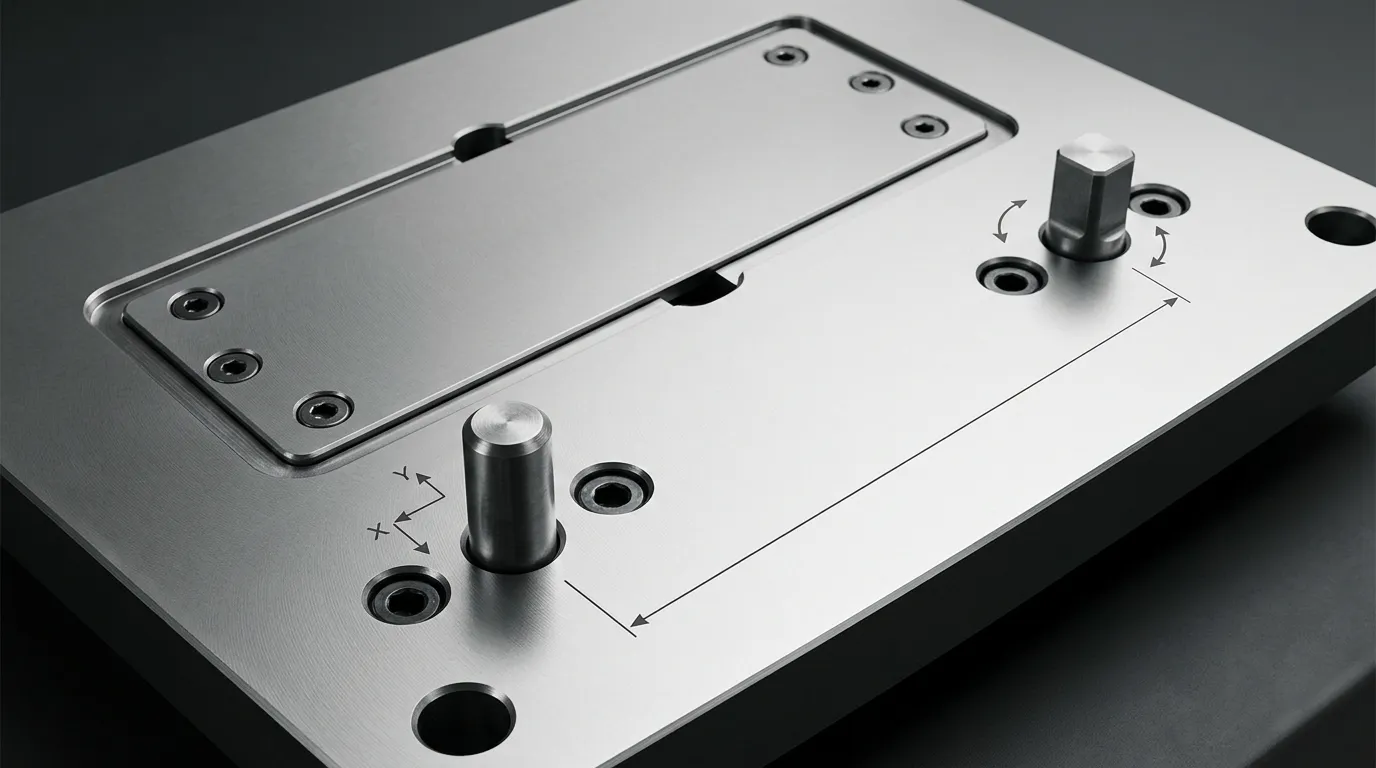
Qué debe controlar la disposición de los pasadores de posición
Before placing any pin, define what the component is allowed to do.
A plate or insert resting on a mating surface can still move in three ways within that plane:
- translate along the X direction;
- translate along the Y direction;
- rotate around an axis perpendicular to the plate.
The positioning-pin layout must control those three in-plane movements. The mating face establishes the seating plane, while screws or clamps retain the component against that face.
This distinction matters because not every mold component performs the same task.
Separate Locating, Guiding, Fastening, and Load Control
| Característica | Rol principal | Lo que no se debe suponer que hace |
|---|---|---|
| Colocación o clavo de varilla | Establecer la ubicación de la placa o del inserto repetible | Sustituye todas las sujeciones o soporta todas las cargas operativas |
| Pasador guía y casquillo | Guía las mitades del molde durante la apertura y el cierre | Proporciona la única ubicación fija para un inserto extraíble |
| Tornillo de montaje | Sujetar o retener el componente | Establish precise, repeatable position by itself |
| Bloqueo lateral o enclavamiento | Complementa la posición final o resiste condiciones laterales particulares | Sustituir un esquema de localización de placas correctamente definido en cada aplicación |
A fixed dowel location and a moving guide system may both contribute to alignment, pero resuelven problemas diferentes. Detailed guide-system selection, Desgaste, and maintenance belong with Pasadores guía de molde, not in the positioning-pin layout itself.
Positioning pins should also not be treated automatically as the main load-carrying elements. Where the mold experiences significant lateral force, final parting-line location or load resistance may require side locks, taper locks, Enclavamientos, Hombros, or other structural features.
Controla tres movimientos en plano sin añadir restricciones redundantes
The layout should constrain only the movements that must be controlled.
A common approach is:
- A primary round locator controls translation in X and Y.
- A secondary locator prevents rotation.
- The mating surface controls seating.
- Screws provide clamping or retention.
Adding more tightly fitted pins does not necessarily increase accuracy. If several locators attempt to control the same movement, small differences in hole position, pin size, Temperatura, or machining error can make the component difficult to assemble.
This condition is called overconstraint. Its effects may include binding, forced assembly, internal stress, damaged locating holes, or inconsistent seating.
Elige el esquema de localización primaria y secundaria
The primary and secondary locators should be selected according to the movement each feature must control.
The correct arrangement depends on component geometry, manufacturing tolerances, Temperatura de funcionamiento, assembly frequency, and the distance between locating points. No one arrangement is best for every mold.
Utiliza el pin redondo principal para establecer la ubicación principal
The primary round pin normally establishes the main in-plane position. Its cylindrical contact controls movement in two directions.
Place this locator relative to the functional mold feature rather than choosing a location only because it is near a convenient plate corner. Por ejemplo, if the position of a cavity insert relative to another machined feature is critical, the primary locator should belong to the same functional datum strategy.
The primary location should also be accessible for:
- drilling and reaming;
- Inspección dimensional;
- Montaje;
- extraction or replacement;
- repair if the hole becomes worn or damaged.
The physical centre of the plate is not automatically the best primary location. Functional control matters more than visual symmetry.
Aliviar la dirección secundaria cuando dos posiciones cerradas de munición se ataquen
A second locator is required to prevent the component from rotating around the primary pin. The problem is that a second tightly fitted round pin also tries to control X and Y.
If the centre distance between the two holes differs slightly from the centre distance between the two pins, the assembly can bind even when each individual diameter is within tolerance.
A diamond pin, relieved pin, or pin-and-slot arrangement avoids this redundant constraint. The secondary locator contacts the mating feature in the direction required to prevent rotation while allowing clearance in the perpendicular direction.
The relief must be oriented correctly. If the relieved direction is turned the wrong way, the secondary locator may fail to control rotation or may still create the centre-distance conflict it was intended to solve.
ASME Y14.5 provides the formal framework for communicating datum relationships and controlled degrees of freedom. Orientación técnica de FARO sobre la ubicación del perno de diamante also illustrates how directional relief reduces redundant constraint.
| Disposición de localización | Comportamiento de las restricciones | Principal ventaja | Limitación principal |
| Dos pasadores redondos ajustados muy ajustados | Ambos bolos intentan controlar dos direcciones | Geometría simple | Sensible al error de distancia central y a la variación térmica |
| Clavo redondo más diamante o alfiler relevado | Primary controls X/Y; secondary controls rotation | Reduce la sobrerestricción | La orientación del relieve debe definirse correctamente |
| Clavo redondo más agujero secundario ranurado | La ranura permite moverse en una sola dirección | Fácil de entender e inspeccionar | La fabricación de la ranura y la geometría de contacto deben controlarse |
| Clavo redondo más localizador flotante | La característica secundaria compensa una mayor variación | Útil cuando la distancia entre centros cambia significativamente | Requisitos de componentes e inspección más complejos |
A floating locator may be useful where centre-distance change is larger than a simple relieved pin can accommodate, such as in long assemblies or components exposed to meaningful temperature differences. It should be selected from verified component data rather than treated as a default solution.
Cuando dos bolos redondos aún pueden ser apropiados
Two round pins are not automatically wrong.
They may work when:
- the pin centre distance is tightly controlled;
- the mating-hole centre distance is controlled from the same datum system;
- one mating condition includes sufficient clearance;
- temperature variation is limited or accounted for;
- the worst-case tolerance condition has been checked;
- the assembly can be installed without forcing.
The decision must be based on the complete tolerance relationship, not nominal dimensions alone.
Establece un espaciado útil entre los pasadores y evita el ensamblaje invertido
Positioning pins should generally have the longest practical locator baseline.
The locator baseline is the effective distance between the two locating points that resists rotation. Increasing that distance reduces the angular effect of the same amount of hole-position error.
This does not mean the pins should always be placed at the farthest possible corners. Wider spacing is useful only when the resulting locations remain structurally sound, manufacturable, accesible, and clear of other mold systems.
Utiliza la línea base práctica más larga del localizador
Consider two locating points separated by a short distance. If the secondary hole shifts slightly, the component rotates around the primary locator.
Now consider the same hole-position shift with the locating points farther apart. The resulting angular change is smaller because the error acts across a longer baseline.
The effect becomes more noticeable at functional features located far from the locators. A small angular error near the pins may produce a much larger positional shift at the opposite end of a long insert or plate.
Orientación práctica para colocar las varillas de MISUMI TechCentral follows the same principle: greater separation between locating points reduces sensitivity to equivalent location error. The exact spacing still depends on the mold design.
Equilibra un mayor espaciamiento con las limitaciones de placas y sistemas
Useful separation must be balanced against other requirements.
Check whether a wider pin pattern creates any of the following problems:
- insufficient material between the locating hole and a plate edge;
- intersection with a cooling channel or cooling plug;
- conflict with mounting screws or counterbores;
- interference with ejector pins, return pins, or ejector-plate features;
- conflict with support pillars or load-bearing areas;
- entry into hot-runner manifold, heater, nozzle, or wiring zones;
- blocked sensor or connector access;
- difficult drilling, reaming, or inspection;
- limited extraction access;
- excessive thermal centre-distance change.
A locator placed near a plate edge may improve the angular baseline, but the remaining plate ligament must still withstand manufacturing, Montaje, y condiciones de funcionamiento. There is no universal edge distance that is safe for every material, plate thickness, Diámetro del pin, or load case.
Haz que el patrón sea asimétrico para ensamblar a prueba de errores
A symmetric two-pin pattern may allow a plate or insert to be rotated or reversed and still appear to fit.
An asymmetric pattern makes the intended orientation unique. This can be achieved by:
- offsetting one locator from the centreline;
- using different distances from adjacent edges;
- staggering the primary and secondary locations;
- combining different locator forms;
- making one orientation physically impossible.
The purpose is not visual variety. It is mistake-proofing.
The pattern should remain unambiguous after the mold has been disassembled for maintenance. A technician should not need to rely on memory or a temporary marking to identify the correct orientation.
Compara la distribución con la geometría del molde y el acceso al servicio
After choosing the locating scheme and approximate spacing, review the complete mold assembly in CAD.
A locating hole is not an isolated feature. Its drilling path, Contrabánio, mating hole, extraction path, and surrounding plate material may pass through several stacked components.
Crea un mapa de obstáculos con sistema de moldes antes de perforar cualquier agujero localizador
Show all relevant systems in the same review model:
- Canales de refrigeración, plugs, Accesorios, and cross-drillings;
- mounting screws and counterbores;
- ejector-pin and return-pin holes;
- ejector-plate movement envelopes;
- Pilares de soporte;
- hot-runner manifolds, nozzles, heaters, and wiring;
- slide and lifter mechanisms;
- sensors and connectors;
- lifting holes and handling features;
- insert pockets and neighbouring replaceable components.
Check hidden paths, not only visible bodies. A proposed locating hole may clear a component in one plate but intersect a cooling drilling or screw counterbore deeper in the stack.
Movement also matters. A hole that is clear in the closed CAD position may conflict with an ejector, slide, or other moving feature during operation or maintenance.
Preserve Plate Strength and Access for Assembly, Inspección, and Removal
A workable layout must remain serviceable throughout the mold’s life.
Confirm that:
- the hole can be drilled and reamed from the intended direction;
- inspection equipment can access the locating surfaces or datums;
- the pin has an extraction method when replacement may be required;
- plate separation does not trap the pin unexpectedly;
- the insert can be removed without damaging the locating surfaces;
- the selected engagement length does not obstruct neighbouring features;
- future hole repair, Bujes, or oversize rework remains possible.
A precise location that cannot be machined, measured, or repaired is not a complete design.
Define Functional Datums, Position Tolerances, and Thermal Relief
The locating pattern must be communicated through a drawing or controlled digital model that reflects the intended function.
Pin diameter alone is not enough. The drawing must also control where the holes are located relative to the component’s functional datums.
Dimensión El patrón localizador a partir de datos funcionales
Select datums according to how the mold plate or insert works in the assembly.
A practical datum strategy should identify:
- the seating surface;
- the primary functional reference;
- the direction that establishes orientation;
- the relationship between the primary and secondary locating holes;
- the critical molded, machined, or mating feature controlled by the layout.
Avoid locating both holes only from arbitrary outside edges unless those edges genuinely control mold function.
Positional tolerancing can communicate the permissible location of the hole axes relative to the datum reference frame. The inspection method should reproduce the same datum setup used by the design.
The article does not prescribe one tolerance value because the correct value depends on the required repeatability, component size, manufacturing process, Capacidad de inspección, and mating clearances.
Validar el ajuste en el peor caso y la condición de temperatura
Check the assembly at the most restrictive combination of permissible dimensions.
The analysis may need to include:
- maximum pin diameter;
- minimum mating-hole diameter;
- position error of the installed pins;
- position error of the mating holes;
- form and perpendicularity variation;
- temperature-related change in pin or hole centre distance;
- orientation and available relief at the secondary locator.
El Sistema ISO 286 de límites y ajustes provides standard terminology and tolerance classes for mating holes and shafts. Parallel dowel-pin categories may also be specified using standards such as ISO 8734 o ISO 2338 Cuando sea aplicable.
These standards provide a framework. They do not select the correct fit for a particular mold automatically.
Thermal movement deserves attention when:
- the locator baseline is long;
- the mating components use different materials;
- assembly and operating temperatures differ;
- one component heats more than the other;
- the mold operates across a wide temperature range.
A relieved secondary direction can accommodate permitted centre-distance change while maintaining rotational control. The relief must still leave enough contact in the controlled direction to meet the location requirement.
Revisa fallos comunes en el diseño antes de publicar el dibujo
Most positioning-pin problems can be traced to a small set of layout mistakes.
| Error de diseño | Consecuencia probable | Dirección correctiva |
| Demasiados pasadores de localización apretados | Ensamblaje forzado o de encuadernación | Eliminar restricciones redundantes o introducir alivio direccional |
| Dos pasadores redondos con distancias centrales incompatibles | Montaje difícil o agujeros dañados | Review fit, position tolerance, and secondary-locator design |
| Localizadores colocados demasiado juntos | Mayor sensibilidad angular | Aumentar la línea base útil cuando sea posible |
| Patrón simétrico | Conjunto de placa o inserción invertida | Escalonar o desplazar un localizador |
| Pines situados desde bordes arbitrarios de placas | Desalineación funcional de características | Dimensión a partir de datos funcionales |
| Orientación incorrecta del perno de diamante | Pérdida de control rotacional o unión continua | Define las direcciones controladas y en relieve en el dibujo |
| El agujero está demasiado cerca de un borde o bolsillo | Ligamento de placa débil o riesgo de grietas | Reposicionar o verificar analíticamente la sección restante |
| Colisión oculta con características de refrigeración o eyección | Retrabajo de mecanizado o daño al sistema | Haz una revisión completa de interferencias CAD |
| Sin acceso a la extracción | Mantenimiento difícil o eliminación destructiva | Añadir una ruta de eliminación o una característica de extracción |
| Comprobación de tolerancia solo nominal | Fallo de ensamblaje en los límites de tolerancia | Validar la condición del peor caso |
| Pasadores guía o tornillos tratados como localizadores fijos finales | Posición inconsistente del inserto o placa | Asigna a cada característica una función definida separada |
| Regla de espaciado copiado | Diseño no verificado | Base placement on geometry, Carga, Tolerancias, and access |
Lista de verificación de diseño previo al lanzamiento
Before releasing the mold positioning pin layout design, confirm the following:
- The functional seating surface and datums are defined.
- The required X, Y, and rotational constraints are identified.
- The primary locator establishes the intended main position.
- The secondary locator controls rotation in the correct direction.
- Redundant directional constraint has been removed where necessary.
- The locator baseline is as long as practical.
- The pattern cannot be assembled in the wrong orientation.
- Plate-edge and pocket ligaments remain acceptable.
- Refrigeración, Eyección, fastening, Apoyo, hot-runner, sensor, and wiring conflicts have been checked.
- Perforación, reaming, Inspección, Montaje, and extraction access are available.
- Worst-case pin size, hole size, Posición, and temperature have been reviewed.
- Drawing notes identify locator function, datums, controlled direction, Encajan, and applicable standards.
- Screws, Pines guía, and interlocks have clearly separated roles.
Preparar la especificación del PIN y la entrega del proveedor
Once the layout has been validated, convert the design into a complete component and hole specification.
Do not send only a nominal pin diameter and overall length. The supplier needs enough information to understand how the component functions in the locating system.
Incluye los requisitos funcionales e inspeccionados en el plano
Dependiendo del diseño, specify:
- whether the component is the primary or secondary locator;
- whether it is round, diamond, relieved, cónico, hombros, or otherwise modified;
- the controlled and relieved directions;
- nominal diameters and lengths;
- mounting and locating portions;
- lead-in geometry;
- removal or extraction features;
- applicable material and heat-treatment requirements;
- surface-finish or treatment requirements where necessary;
- datum references and positional controls;
- mating-hole requirements;
- inspection characteristics and required records;
- applicable ISO or drawing standards;
- drawing revision and quantity.
The mounting fit and the locating fit should be treated as separate functional decisions. One portion may retain the pin in a plate, while another portion locates the mating component. The exact fit must be validated from the application, tolerance analysis, and qualified manufacturing data.
Decide entre un componente de localización estándar y uno personalizado
A standard component is usually preferable when its geometry, Tolerancia, Material, removal method, and available lengths meet the design.
Custom geometry may be justified when the layout requires:
- a special relieved direction;
- a nonstandard shoulder;
- a tapered locating portion;
- an extraction thread;
- an unusual engagement length;
- restricted installation access;
- a special interface between mounting and locating diameters.
Sunshine lists straight, cónico, and drawing-based custom options on its Página de producto de Dowel-Pin. Its website also presents customization of dimensions, Tolerancia, Material, y acabado superficial. These are listed offerings rather than proof that every drawing or tolerance can be produced, so project-specific capability should be confirmed before release.
For broader guidance on deciding between catalogue components and customized parts, véase Piezas estándar de molde.
After the locator roles, Dimensiones, datums, Tolerancias, Requisitos de materiales, Condiciones de funcionamiento, and inspection needs are defined, the drawing can be reviewed with a component supplier. Sunshine’s Página de contacto provides a route for discussing standard or custom locating-pin requirements without replacing the mold designer’s own fit, Fuerza, and tolerance validation.
Compartir:



Escrito por Sunshine
Al sol, Somos un fabricante y proveedor profesional de componentes de moldes de precisión, ofreciendo una amplia gama de productos para aplicaciones de estampado y moldes de inyección. Nuestro enfoque principal es el punzonamiento de troqueles, Pasadores y fundas eyector, y postes guía y casquillos. Con mecanizado CNC avanzado, Control de calidad estricto, y una fuerte capacidad de producción, Garantizamos la fiabilidad, Piezas de alta precisión, junto con componentes estándar en stock para un suministro global rápido y eficiente.
NOTICIAS
CONSIGUE EL SERVICIO
Con piezas de calidad para todos los presupuestos y personal amable formado para que tu visita sea informativa y sin complicaciones.
