



Mold Limit Pin Installation Guide: Seating, Retención, and Access
A mold limit pin must do more than fit inside its mounting hole. It must seat against the correct reference surface, project to the drawing-defined height, remain securely retained, and still be accessible when inspection or replacement is needed.
Los pines límite pertenecen al grupo más amplio de Piezas estándar de molde (Inferido), but catalog dimensions alone do not determine whether a pin can be installed correctly. The mold assembly drawing, component drawing, bill of materials, Condición del calibre de montaje, and retention design must agree before installation begins.
This guide covers mechanical limit or stop pins that establish a plate-travel, contact, or impact-control position. It does not provide universal fit, Par motor, insertion-force, seat-depth, or hardness values. Those requirements must come from the approved mold documentation.
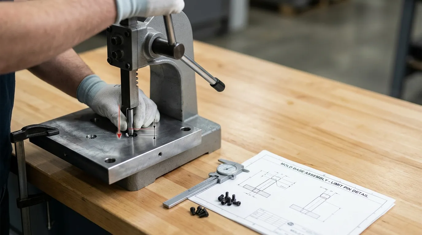
Confirma el funcionamiento del PIN antes de instalarlo
The first step is not pressing the pin into the plate. It is confirming what the component is expected to do.
Términos como Pin límite, Stop pin, Guía de pasador, Clavo de varilla, Clavija de retorno, y Pasador eyector are sometimes used inconsistently. Two pins may look similar while performing different functions inside the mold.
Distinguish Limit Pins from Guide, Dowel, Return, and Ejector Pins
| Componente | Función principal | Relación típica | Principal preocupación de instalación |
|---|---|---|---|
| Pasador límite o de parada | Establishes a travel, contact, or impact-control position | Contacta o limita el movimiento de una placa o mecanismo | Proyección instalada, Asientos, Retención, and contact height |
| Guía o pasador de guía | Alinea secciones de molde móviles y estacionarias | Pasa por un casquillo guía de apareamiento | Alineación, fit with the bushing, Lubricación, y desgaste |
| Clavo o clavo localizador | Localiza componentes entre sí | Encaja entre placas o partes que deben mantener su posición | Precisión posicional y resistencia al movimiento relativo |
| Pasador de retorno | Ayuda a devolver un mecanismo relacionado con el eyector | Funciona con el conjunto eyector durante el cierre del molde | Travel, interference, and return timing |
| Pasador eyector | Empuja la pieza moldeada desde la cavidad o núcleo | Se mueve a través del sistema de eyección y la zona de moldeo | Longitud, Autorización, motion, and contact with the molded part |
Do not assume that a pin is a limit pin because of its shape or location. Check the assembly drawing and BOM designation. The drawing should show which plate carries the pin, which surface contacts it, and what movement the pin is intended to control.
If the component is part of the mold’s alignment system, refer to the separate guide on Pasadores y casquillos de molde rather than applying stop-pin installation logic.
Lee el dibujo y la lista de materiales como instrucciones de control
Before removing an old pin or fitting a replacement, verificar:
- Revisión actual del dibujo
- Número de pieza del componente
- Cantidad y ubicación
- Instalación de gestión
- Diámetro de la carrocería y longitud total
- Hombro, cabeza, Brida, or threaded features
- Llamada de ajuste de agujeros o eje
- Profundidad del agujero de montaje
- Superficie de referencia de asientos
- Proyección instalada requerida
- Método de retención
- Acceso con sujetadores
- Método de extracción o eliminación
La Organización Internacional de Normalización Sistema ISO 286 provides recognized terminology for hole and shaft tolerances. It does not tell the installer which fit is correct for a specific limit pin. The approved drawing must make that decision.
Stop the work if the drawing, BOM, and actual component conflict. Additional force will not correct an incorrect part number, obsolete revision, or mismatched geometry.
Prepare the Mold, Pin, and Mounting Feature
Preparation determines whether the pin reaches its intended seat without damaging the bore or plate.
The mold must be safely supported, the component must match the documentation, and the mounting feature must be clean and dimensionally suitable before insertion starts.
Aislar y soportar el moho de forma segura
A mold may contain electrical, hydraulic, pneumatic, mechanical, gravitational, or spring-loaded energy. Control those hazards under the approved workplace procedure before disassembly or installation.
El principio general es coherente con los requisitos de OSHA para la Control de energías peligrosas, although the exact legal and procedural requirements depend on the country, Máquina, and workplace.
Before working on the pin:
- Isolate the molding machine and connected systems.
- Release or restrain stored energy.
- Support plates that could shift after a component is removed.
- Position the mold so installation force can be applied in line with the pin axis.
- Confirm that no person is exposed to an unsupported moving plate or ejector assembly.
This is not a substitute for local lockout, Mantenimiento, or lifting procedures.
Inspecciona el pasador de repuesto
Compare the replacement pin with the latest component drawing rather than relying only on the old pin.
Comprobado:
- Diámetro del cuerpo
- Longitud total
- Dimensiones de hombro o cabeza
- Condición de contacto facial
- Tamaño del hilo y daño del hilo
- Biselados y estado de los bordes
- Marcado superficial o corrosión
- Rectitud y deformación visible
- Número de pieza o identificación rastreable
SunshinePro’s listed Mold Limit Pin product includes product-specific material, Tolerancia, dureza, threaded-feature, and customization information. Those figures apply only to the listed product configuration. They must not replace the project drawing or be treated as universal installation values.
Questions involving wider material, Tolerancia, Fin, or incoming-QC requirements belong under the broader topic of Piezas de molde de precisión.
Inspect the Bore, Counterbore, and Seating Face
A correct pin can still install incorrectly when the receiving feature is damaged or contaminated.
Inspect the mounting area for:
- Chips, grease deposits, hardened residue, or corrosion
- Rebabas alrededor de la entrada del agujero
- Metal elevado alrededor de un alvo
- Marcado o transferencia de material dentro del tubo
- Distorsión u ovalidad
- Superficies de asiento agrietadas o dañadas
- Profundidad incorrecta del agujero
- Reestructuración no aprobada
- Daños de intentos anteriores de retirada
Remove contamination using an approved cleaning method, but do not enlarge, Polaco, grind, or reshape the bore simply to make the replacement fit.
Manufacturer assembly documentation commonly requires installers to check counterbores, remove burrs, inspect seating surfaces, and confirm component height before final assembly. The same control principle applies here: clean geometry must be verified before force is applied.
Establece el asiento correcto y la proyección instalada
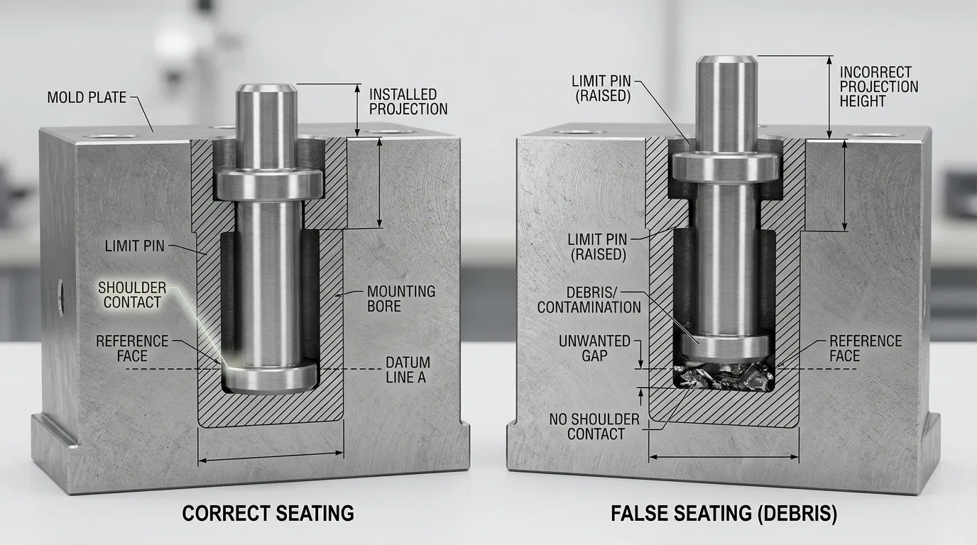
A pin is not acceptable merely because it appears fully inserted.
Its axial position must be established by the intended reference face. Depending on the design, that may be a shoulder, cabeza, Brida, counterbore, Retenedor, or another drawing-defined surface.
Identificar la cara de referencia y el dato de medición
The drawing should answer two separate questions:
- Where does the pin stop during installation?
- From which mold surface is its exposed height measured?
These surfaces are not always the same.
Por ejemplo, a shoulder may seat inside a counterbore while the installed projection is measured from the outer plate face. A threaded or retained design may establish axial position through a head or clamping component rather than through the bottom of the hole.
Use one controlled datum for all measurements. Record that datum with the measured projection so another technician can repeat the inspection later.
A vague instruction such as “press until fully seated” is inadequate unless the seating surface and final height are defined.
Evitar que se asenten de forma falsa en agujeros ciegos
Blind holes require special attention because the pin can contact the hole bottom before its intended shoulder or reference surface reaches the seat.
False seating may result from:
- Profundidad insuficiente del agujero
- Astillas o escombros en la parte inferior
- Una muela bajo el hombro
- Residuos atrapados o metal dañado
- Una longitud incorrecta del pin
- Una geometría de cabeza o hombro desajustada
- Modificación previa no aprobada del ánimo
Common warning signs include:
- Proyección instalada excesiva
- Un hueco visible bajo el hombro
- Resistencia a la inserción inesperadamente alta
- Un alfiler que parece inclinado
- Diferentes alturas instaladas entre pines nominalmente idénticos
Do not apply additional force when these symptoms appear. Remove the pin using the approved method, inspect the hole and component, and compare both with the drawing.
Comprueba la altura común cuando varios pasadores comparten contacto
Several limit pins may form one contact plane. Equal pin lengths do not guarantee equal installed heights because bore depth, seat condition, Escombros, Distorsión de la placa, and component geometry can vary.
When multiple pins are intended to contact together:
- Measure every pin from the same datum.
- Compare actual installed projections.
- Check the mating plate for rocking.
- Look for one pin contacting before the others.
- Inspect contact surfaces for uneven marking.
- Confirm that no pin is carrying contact because another pin is seated too low.
The drawing or approved engineering specification must provide the allowable variation. Do not invent an acceptance tolerance from a different mold or catalog.
Instalar el pasador con soporte axial controlado
Once the component and mounting feature have been verified, install the pin in the direction specified by the drawing.
- Confirm the required fit and installation direction.
- Support the plate close to the mounting area.
- Align the pin axis with the bore axis.
- Place installation tooling against an approved non-functional surface.
- Apply controlled axial force.
- Monitor the pin for tilt, Puntuación, shaving, or abnormal resistance.
- Stop when the drawing-defined seating condition is reached.
- Measure the installed projection rather than accepting insertion force as proof of completion.
- Inspect the surrounding plate and exposed pin surfaces for damage.
For an interference-fit arrangement, the fit class influences the required assembly force and future removability. That does not justify estimating the force by feel or copying a fit from another component.
Avoid uncontrolled hammer impact. Side loading can cock the pin, damage the hole entrance, deform the plate, or mark the functional contact face.
Heating, Refrigeración, surface modification, or lubrication should be used only when the approved installation procedure permits it and defines the applicable conditions.
Para cuando el pin no se instale correctamente
Stop the operation if you observe:
- Resistencia repentina o inconsistente
- Inclinación del pasador
- Afeitado de metales
- Puntuación de calibre
- Distorsión de placa
- Una cara de contacto dañada
- Proyección excesiva
- Un hombro que no llega hasta su asiento
- Un ajuste que es inesperadamente flojo
Recheck the part number, fit callout, Diámetro del diámetro, hole depth, seat geometry, and component condition. A forced installation can conceal the original mismatch while creating a second problem in the plate.
Empareja la seguridad de retención con el acceso futuro al servicio
The pin’s fit and its axial retention are related but not always identical.
Some designs depend mainly on interference. Others use screws, Hilos, blocks, plates, or trapped heads. The correct choice is the one shown in the approved design, not the method that is easiest to apply during maintenance.
Comparar métodos de retención por seguridad y disponibilidad
| Método de retención | Característica principal | Consideración de acceso al servicio | Riesgo principal a comprobar |
| Interference fit | El ajuste radial proporciona retención | Removal may require rear access, pulling equipment, or plate disassembly | Daño en el ánimo o pérdida de retención tras la retirada repetida |
| Pasador roscado o tornillo de retención | El fijador mecánico controla el movimiento axial | El sujetador debe permanecer accesible tras el montaje | Incorrect torque, damaged threads, or inaccessible fastener |
| Diseño con tornillo | Un tornillo o abrazadera separado asegura el pasador | Puede ser reparable si la abrazadera queda expuesta | Movimiento de la pinza o acceso insuficiente |
| Placa o bloque de retención | Una placa o bloque atrapa el pasador | Puede permitir una retirada controlada, pero añade fijaciones y mecanizado | Retenedor instalado en la secuencia incorrecta |
| Cabeza o hombro atrapados | Las placas adyacentes capturan el componente | A menudo es necesario separar las placas para su retiro | El mantenimiento futuro puede ser complicado |
| Compuesto de retención | El adhesivo sostiene una unión cilíndrica | Hay que planificar las condiciones de extracción y curación | Incorrect gap, Contaminación, Temperatura, or unapproved use |
Retaining compounds are not a general cure for a loose or damaged bore. Products such as LOCTITE 638 have defined gap, Preparación, cure, Temperatura, y requisitos de materiales. Use one only when the component design and engineering instructions approve it.
Confirm Front, Rear, and Extraction Access
Before final assembly, confirm how the pin will be inspected and removed later.
Check whether:
- Se puede alcanzar un tornillo de retención desde la parte frontal
- Un sujetador de acceso trasero queda bloqueado por otra placa
- Un hilo de tirador permanece expuesto
- Un orificio pasante permite un soporte o retiro controlado
- Un pasador de agujero ciego tiene un método de extracción definido
- Una placa de retención puede retirarse sin desmontar sistemas no relacionados
- The pin’s orientation leaves access to flats, Hilos, or fasteners
- Una posterior eliminación ejercería fuerza contra una superficie sensible de la placa
A retention method can be mechanically secure and still be a poor maintenance design. Record any plate separation or special tooling required for removal.
Mide y valida la instalación
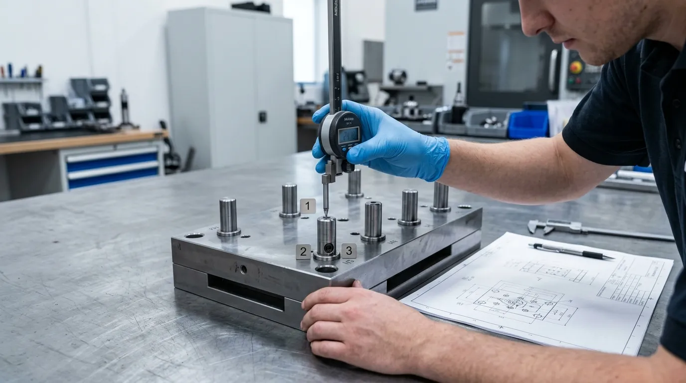
Installation is complete only after dimensional and functional checks confirm that the pin is seated, Retuvo, accessible, and operating as intended.
Use the approved inspection equipment and the same datum established before installation.
- Measure the installed projection.
- Confirm the pin’s orientation.
- Verify the retention feature.
- Check screw or retainer access.
- Compare the heights of all pins that share contact.
- Check the mating plate for rocking or premature contact.
- Confirm clearance from nearby components.
- Perform an approved test fit or controlled dry cycle.
- Record the result.
Manuales de montaje del fabricante Maestros de moldes illustrate the broader importance of drawing review, seating checks, installed-height measurement, clearance verification, and controlled test fitting. The exact acceptance values for a limit pin still come from its own mold documentation.
Record Installed Height, Retención, and Access
The installation record should identify:
- Número de molde o herramienta
- Revisión del dibujo
- Número de la pieza del pin
- Datum de medición
- Proyección instalada real
- Método de retención
- Estado de los sujetadores
- Dirección de acceso frontal o trasera
- Método de extracción
- Fecha e inspector
- Approved deviations, Si es que hay
Photographs of the installed pin, seat, and access arrangement may also help future maintenance teams understand the accepted condition.
Utiliza un ciclo controlado de ajuste de prueba o seco
Follow the approved machine and mold procedure for any movement test.
Observe:
- Secuencia de contacto
- Recorrido de la placa
- Resistencia inusual
- Rocking
- Interferencia
- Movimiento de sujetadores
- Contacto desigual del pasador
- Un mecanismo que se detiene antes o después de la posición prevista
Stop the test if the mold does not move or contact as the drawing intends. Do not proceed directly to full-speed production to see whether the problem resolves itself.
Solucionar problemas comunes de instalación de pasadores de límite
| Síntoma | Causas probables | Respuesta requerida |
| El alfiler está demasiado alto | Burrs, Escombros, insufficient blind-hole depth, wrong pin length, wrong shoulder geometry, false bottoming | Remove using the approved method, inspect the seat and hole depth, and compare the part with the drawing |
| El pasador queda demasiado bajo | Incorrect seat depth, damaged reference face, wrong component, unapproved material removal | Stop and obtain engineering review; do not shim or modify the pin without approval |
| El pasador está inclinado | Cocked insertion, damaged bore, Carga lateral, distorted plate, incorrect fit | Remove and inspect the bore and pin; check axial support and alignment |
| El pasador está suelto | Worn or oversized bore, wrong diameter, missing retention, incorrect fit | Do not rely on additional force or adhesive; assess bore repair, redesign, o sustitución |
| Un pin contacta primero | Unequal projection, debris under another pin, mating-surface variation, incorrect component length | Mide cada pin de un solo datum e inspecciona el plano de contacto |
| No se puede alcanzar el retenedor | Orientación incorrecta, blocked fastener, poor assembly sequence, insufficient access planning | Correct before final assembly; document any required plate removal |
| El pasador se afloja repetidamente | Incorrect retention, damaged bore, changing load path, unsuitable geometry | Escalar para revisión de diseño e ingeniería |
Installation should stop when:
- The drawing is unavailable or contradictory.
- The replacement component cannot be positively identified.
- The bore is cracked, enlarged, distorted, or heavily damaged.
- The seat no longer provides a stable reference.
- The required projection cannot be achieved.
- The specified retention cannot be installed or accessed.
- Several pins cannot be brought to the intended contact condition.
- The mold movement does not match the drawing after installation.
Do not use generic drilling, molienda, welding, Aplastamiento, bonding, or oversizing methods as an automatic repair. Each can change the plate geometry, component fit, serviceability, or contact position.
Decide cuándo el pasador o la característica de montaje necesita ser reemplazado o rediseñado
A standard replacement may be suitable when the current drawing remains valid and the bore, seat, Ajuste, Retención, and access arrangement are undamaged.
Engineering or supplier review is appropriate when:
- The existing bore is worn or oversized.
- The reference seat is damaged.
- The original drawing does not match the mold.
- A discontinued or altered pin geometry is present.
- The retention method cannot be serviced.
- Required projection cannot be achieved from the existing seat.
- The pin repeatedly loosens.
- Several pins do not share contact correctly.
- A standard component does not match the existing arrangement.
For a replacement review, Prepárate:
- Dibujado actual del pin
- Dibujo de ensamblaje de molde
- Dimensiones y geometría del pin
- Diámetro y profundidad del orificio de acoplamiento
- Proyección instalada requerida
- Requisitos de materiales y tratamiento térmico
- Método de retención
- Limitaciones de acceso y extracción
- Fotografías o una muestra física cuando sea apropiado
SunshinePro afirma que suministra un sistema dedicado Producto del pasador de límite de molde and can discuss custom mold accessories from drawings or samples. The exact material, Tolerancia, Geometría, retention feature, and production feasibility still require project-specific confirmation.
Lista de verificación para la instalación de pasadores de límite de moho
Before accepting the installation, confirm that:
- The component’s actual function has been identified.
- The current drawing and BOM revision have been checked.
- The mold and machine have been safely isolated.
- The pin dimensions and condition match the documentation.
- The mounting bore, counterbore, and seating face are clean and undamaged.
- The correct reference face and measurement datum are known.
- Blind-hole depth and bottom clearance have been checked where applicable.
- The pin was installed with controlled axial support.
- No scoring, shaving, tilt, or plate distortion is present.
- The specified retention method has been completed.
- Fastener and extraction access remain available.
- Installed projection has been measured.
- Multiple-pin contact has been checked where required.
- A controlled test fit or dry cycle has been completed.
- Actual measurements and observations have been recorded.
If the pin, Diámetro, seat, or retention arrangement does not match the approved documentation, do not force the installation. Send the component drawing, mating-hole dimensions, required projection, and access details through the Página de contacto de SunshinePro for a project-specific review.
Compartir:



Escrito por Sunshine
Al sol, Somos un fabricante y proveedor profesional de componentes de moldes de precisión, ofreciendo una amplia gama de productos para aplicaciones de estampado y moldes de inyección. Nuestro enfoque principal es el punzonamiento de troqueles, Pasadores y fundas eyector, y postes guía y casquillos. Con mecanizado CNC avanzado, Control de calidad estricto, y una fuerte capacidad de producción, Garantizamos la fiabilidad, Piezas de alta precisión, junto con componentes estándar en stock para un suministro global rápido y eficiente.
NOTICIAS
CONSIGUE EL SERVICIO
Con piezas de calidad para todos los presupuestos y personal amable formado para que tu visita sea informativa y sin complicaciones.
