



Inspección de desgaste de pasadores de límite de moho: Mediciones y pistas de fallo
A proper mold limit pin wear inspection combines visual evidence with controlled dimensional measurements. A polished contact face alone does not prove that the pin is damaged, while a pin that appears clean may still have lost diameter, effective height, or straightness.
The pin should be compared with a controlled drawing, an approved inspection record, a qualified spare, or a documented historical baseline. There is no universal wear allowance or replacement cycle that applies to every mold.
Los pines límite son una parte del sistema más amplio de reemplazables Piezas estándar de molde (Inferido). This guide focuses only on how to inspect their wear, interpret failure clues, and document the next technical action.
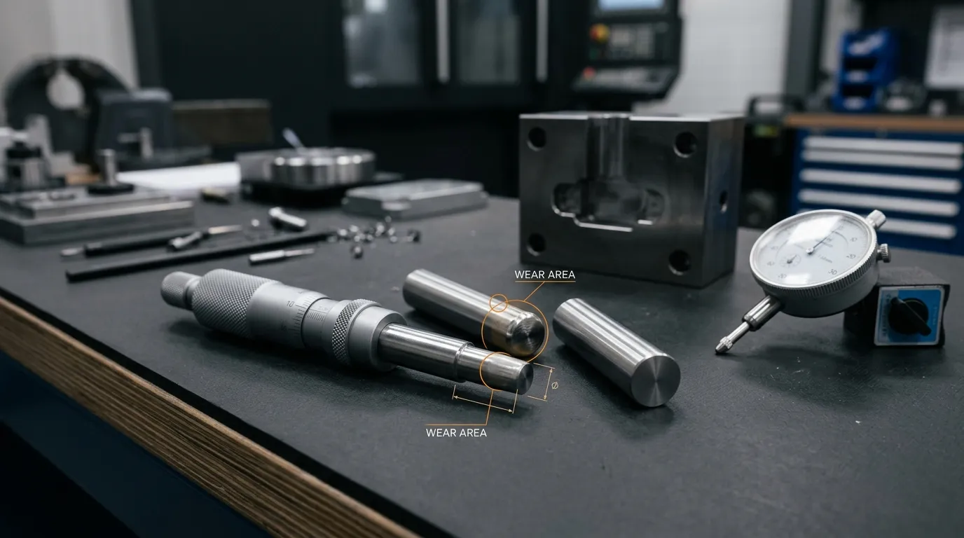
Establecer una referencia de inspección segura y válida
Before opening, removing, or measuring a limit pin, isolate the molding machine and control all stored energy according to the procedures that apply at the facility. Stored hydraulic pressure, Manantiales, suspended mold sections, gravity, and moving plates can remain hazardous even after the machine has stopped.
Para los lugares de trabajo en EE. UU., OSHA 29 CFR 1910.147 provides requirements for controlling hazardous energy during servicing and maintenance. Other countries and regions have their own requirements, so the applicable local procedure must control the work.
Before measurement:
- Support the mold and any movable assembly securely.
- Record the pin’s position before removal.
- Photograph visible damage before cleaning it away.
- Remove oil, loose debris, corrosion residue, and dirt from measuring surfaces.
- Check for burrs that could distort the reading.
- Allow the pin and reference equipment to reach a stable measurement condition.
- Confirm which drawing revision or baseline will be used.
Confirm the Pin by Function, Not Name Alone
Los términos Pin límite, Stop pin, y Pasador de tope may describe similar travel-limiting functions, but naming is not consistent across mold designs and suppliers.
Identify the component by asking:
- Which plate or assembly does it stop?
- Where is its contact face?
- Which surface does it contact at the end of movement?
- Does it carry stopping load, guide movement, return a plate, eject a part, or locate an assembly?
A return pin, Pasador eyector, Guía de pasador, dowel, or locating pin should not be assessed using a limit-pin procedure simply because it has a similar cylindrical shape.
Elige la referencia antes de tomar las mediciones
A measured value has little meaning until it is compared with a valid requirement. Use the strongest available reference in this order:
- Dibujo controlado de componentes o moldes
- Especificación OEM o estándar de inspección aprobado
- Informe de inspección aprobado anteriormente
- Repuesto nuevo cualificado
- Mediciones históricas desde la misma posición del pasador
- Comparación relativa con pasadores coincidentes del mismo conjunto
Confirm the units, datum surfaces, Tolerancias, and drawing revision. A nominal length measured from the wrong shoulder or reference face may produce a precise but useless result.
When a result is close to an acceptance limit, measurement uncertainty also matters. ISO 14253-1:2017 addresses how specification limits and measurement uncertainty affect conformity decisions.
Manufacturing tolerances listed on a supplier’s product page should not automatically be treated as service-wear limits. New-part acceptance and continued-service acceptance are different engineering decisions.
Inspecciona el pasador y su sistema de contacto antes de medir
Begin with a systematic visual examination. Use strong lighting and magnification where needed, but inspect the surrounding components as well as the pin itself.
Check these areas:
- Contacto o parar la cara
- Borde exterior de la cara de tope
- Vástago cilíndrico
- Transiciones de diámetro
- Hombro o cabeza
- Características de hilos y retención
- Superficie de asientos
- Superficie de tope correspondiente en el molde
- Otros pasadores que comparten la misma carga de frenado
Look for polishing, flattened areas, mushrooming, Puntuación, metal transfer, Pitting, Corrosión, cracks, chipped edges, Daños por hilo, and fretting around retained interfaces.
The mating stop surface deserves equal attention. An indentation, Burr, embedded particle, or worn pocket can change the functional stopping position even when the pin itself remains close to its original length.
Separar el pulido normal de testigos del daño anormal
A centered and stable polished witness mark may simply show where normal contact occurs. It becomes more concerning when the pattern changes shape, moves toward one edge, or differs significantly between pins in the same set.
| Observación | Interpretación inicial |
|---|---|
| Centered, even polishing | Puede indicar un contacto normal y equilibrado |
| Marca unilateral o diagonal | Possible misalignment, unequal height, o de carga lateral |
| Cara de registro aplanada | Impacto repetido o carga concentrada |
| Borde de setas | Deformación plástica en la cara de contacto |
| Puntuación longitudinal | Abrasive debris, Contacto deslizante, o desalineación |
| Metal manchado o pastilla | Posible desgaste o desgaste por adhesivo |
| Grietas o bordes astillados | Daños estructurales que requieren una escalada inmediata |
| Óxido o picaduras | Pérdida de materiales relacionada con la corrosión o malas condiciones de almacenamiento |
These observations are clues, not final diagnoses. Desgaste unilateral, por ejemplo, may come from a bent pin, unequal pin heights, Desgaste por sistema guía, a damaged seat, or an uneven mating surface.
Measure Diameter Wear, Taper, and Ovality
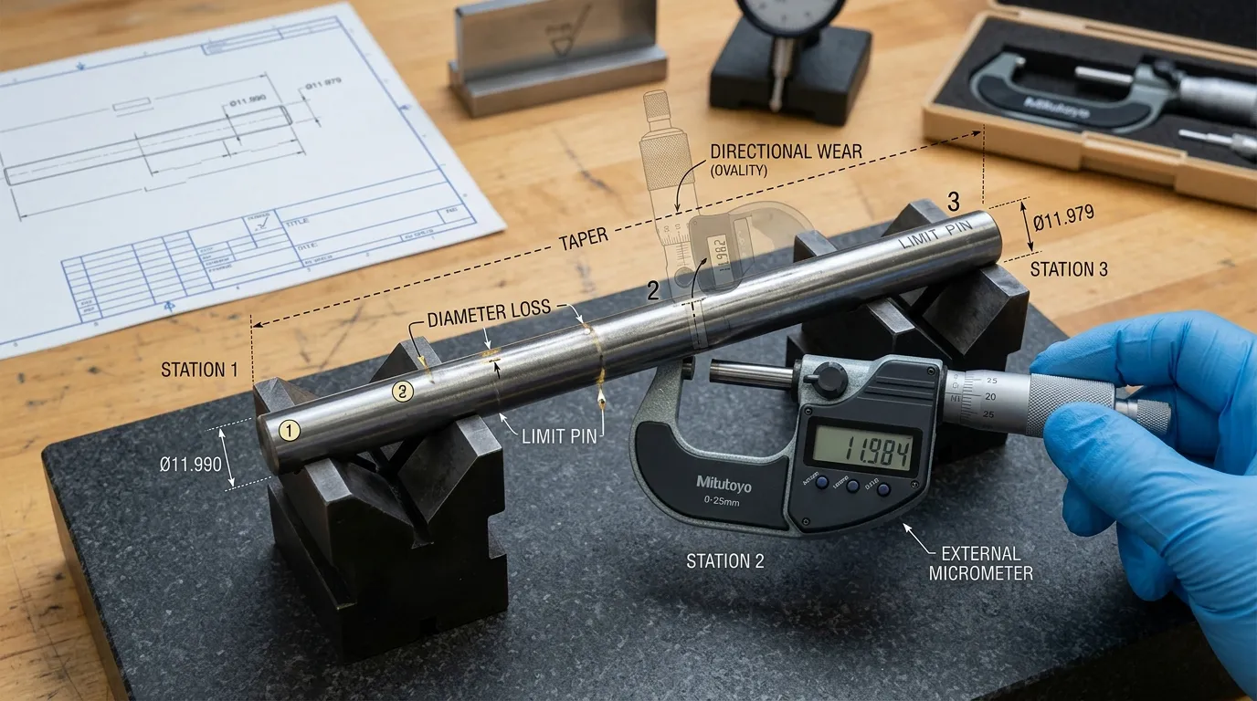
A single diameter reading cannot describe the complete wear condition of a limit pin. Measurements should be taken at repeatable axial locations and in more than one rotational orientation.
An external micrometer is usually more suitable than a caliper when small diameter changes must be evaluated. ISO 3611:2023 defines design and metrological characteristics for external micrometers. Calipers are useful for preliminary checks, but their capability must match the tolerance and expected amount of wear. Their general metrological characteristics are covered by ISO 13385-1:2019.
A practical measurement sequence is:
- Mark the measurement locations along the shank.
- Measure near the upper working area.
- Measure near the centre.
- Measure near the lower working area or seat, where accessible.
- At each location, take readings in at least two rotational orientations.
- Record the position and orientation of every reading.
- Compare the results with the drawing, spare, baseline, and corresponding pins.
This pattern helps separate several conditions:
- Diameter loss: The measured diameter is smaller than the approved reference.
- Taper: Diameter changes progressively along the pin’s length.
- Ovalidad: Readings differ when the pin is rotated at the same axial position.
- Vestimenta local: One short area shows greater loss than the rest of the shank.
Directional diameter loss often supports an investigation into side loading or alignment. Progressive axial wear may indicate contact in a specific working zone rather than uniform material loss.
Do not assign a universal rejection value. The acceptable difference depends on the controlled design, Ajuste, carga, and function of the individual mold.
Check Length, Protrusion, and Effective Stop Height
Overall length is not always the most important axial measurement. The functional dimension may be free length, installed protrusion, shoulder-to-face distance, recess depth, or assembled stop height.
First identify the dimension that actually controls plate movement. Then check:
- Longitud total o libre
- Deformación de cara de contacto
- Protuberancia instalada
- Asientos en el hombro
- Compromiso del hilo
- Profundidad del asiento
- Condición de superficie de acoplamiento
- Altura relativa de los pines coincidentes
A pin may measure correctly after removal but still sit too low because of debris under the shoulder, Daños por hilo, seat wear, or an incorrect replacement geometry. The opposite can also occur: the pin may appear shortened when the real loss is an indentation in the opposing stop surface.
Use a height gauge, depth micrometer, height micrometer, or another suitable setup based on the controlled datum and accessibility. The setup must be rigid enough to produce repeatable results.
Compara todos los pines que comparten la carga de frenado
Several limit pins may work together to stop the same moving plate. Their effective heights should be compared because one high pin can contact first and carry more load than the others.
Comprueba si:
- Contact patterns appear on all corresponding pins.
- Protrusion or effective height is consistent.
- One pin has a larger polished or deformed area.
- One position shows deeper indentation on the mating surface.
- A previously replaced pin differs from the remaining set.
- One pin contacts before the plate becomes parallel.
Replacing only the visibly damaged pin may not solve the problem if the set has unequal heights or if another component caused the load imbalance.
Check Runout, Bending, and Straightness
A pin subjected to side loading, collision, or severe misalignment may bend without showing major diameter loss.
Where the geometry permits, support the clean pin on suitable datum surfaces or V-blocks and use a dial indicator to measure variation during rotation. Record the indicator position and support arrangement so the test can be repeated.
Before accepting the result, Comprobar para:
- Rebabas bajo los puntos de soporte
- Sucia en los bloques en V
- Superficies cilíndricas dañadas
- Hombros irregulares
- Mala alineación de los indicadores
- Fuerza medidora excesiva
- Movimiento del soporte
Runout, Rectitud, and coaxiality are related but not interchangeable terms. ISO 1101:2017 provides the geometrical tolerancing framework for form, Orientación, Ubicación, y runout. Straightness terminology is further defined in ISO 12780-1:2011.
The total indicated variation from a workshop setup should not automatically be treated as the drawing’s straightness error. It is an inspection result that must be interpreted against the specified geometry and measurement method.
When bending or directional wear is found, inspect the mold’s alignment system. Desgastado Pasadores y casquillos de molde can allow plate movement that places abnormal side load on a limit pin.
Interpreta los patrones de desgaste sin saltar directamente a la causa raíz
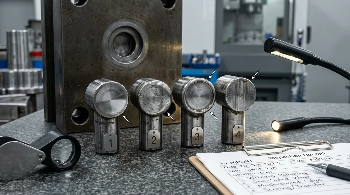
Use each wear pattern to guide further inspection rather than treating it as proof.
| Pista de fallo | Posibles causas | Comprobaciones de confirmación | Respuesta inmediata |
| Marca de testigo unilateral | Desalineación, unequal pin height, angled mating surface | Compare matched-pin heights, guide condition, plate parallelism | Continúa con el diagnóstico antes de cambiar el pasador |
| Cara aplanada o con hongos | Impacto repetido, overtravel, Área de contacto insuficiente, unequal loading | Check effective height, stroke, mating surface, other pins | Mide la pérdida axial y aumenta si la deformación está activa |
| Puntuación longitudinal | Escombros, desgaste abrasivo, Contacto deslizante, Mala alineación | Inspect bore or surrounding surface, Contaminación, Sistema de guía | Eliminar la contaminación y evaluar la pérdida de diámetro |
| Acalorado o transferencia de metales | Alta fricción, Desgaste por adhesivo, poor surface compatibility | Look for transferred material, heat discoloration, rough mating surface | Detener el daño continuo e investigar el par de contactos |
| Pérdida de diámetro local | Desgaste por contacto concentrado o abrasivo | Diámetro de la aplicación en varias posiciones axiales | Compárese con dibujos y datos históricos |
| Reducción u ovalidad | Directional wear, side load, uneven support | Rotate measurements, inspect alignment and seating | Determina si el desgaste es estable o progresa |
| Exceso de descorrido | Bending, collision, Carga lateral | Repeat indicator setup, inspect guide system and plate movement | Revisión de ingeniería antes de la reutilización |
| Picaduras o corrosión | Humedad, Exposición química, poor storage | Examina los componentes cercanos y las condiciones de almacenamiento | Evaluar la profundidad y el efecto estructural |
| Grietas o bordes astillados | Impact fatigue, sobrecarga, material damage | Inspeccionar con la ampliación adecuada o el método NDT aprobado | Retirar el servicio y escalar |
| Daño en el hilo o el hombro | Loosening, improper seating, repeated movement | Check seat, Compromiso, retention and installed height | Corregir el problema de retención antes de reemplazarlo |
Abnormal sound, pegado, plate travel changes, Flash, or mismatch can justify an unscheduled inspection. They do not independently prove that the limit pin is the failed component.
Decide Whether to Continue, Monitor, Replace, or Escalate
The final decision should combine dimensional results, visible condition, functional evidence, and the approved acceptance criteria.
| Decisión | Condición adecuada |
| Continuar en servicio | Measurements meet approved criteria, contact is stable, no structural damage is present, and associated components are acceptable |
| Monitor | Minor measurable change is permitted, the condition is stable, and a documented reinspection plan is approved |
| Replace | The pin is outside its controlled specification, has unacceptable height variation, Deformación severa, damaged retention features, Grietas, Chips, or active galling |
| Revisión de ingeniería | No valid specification exists, results conflict, uncertainty is too high, damage keeps returning, or system-level misalignment is suspected |
A pin should not be polished or reground automatically. Material removal can change its effective length, stop height, contact timing, y distribución de carga. Serviceability depends on the component’s function and approved dimensional limits.
Generic cycle-count recommendations are also unreliable. Two molds using similar pins may create very different impact loads, alignment conditions, contamination exposure, and maintenance histories.
Registrar la inspección y evitar errores comunes de medición
A useful inspection record should include:
- Identificación de moho
- Posición de clavado
- Número de dibujo y revisión
- Referencia utilizada
- Instrumento de medición y resolución
- Ubicaciones de medición
- Valores y unidades registrados
- Fotografías
- Condición de superficie de acoplamiento
- Estado de los pines coincidentes
- Síntomas operativos relevantes
- Destino final
- Disparador de reinspección o intervalo aprobado
Consistent records make it possible to see whether wear is stable or accelerating.
Common errors include:
- Measuring through oil, Tranquilidad, dirt, or burrs
- Medición de un componente caliente frente a datos de referencia a temperatura ambiente
- Tomando solo una lectura de diámetro
- Cambio de ubicación de medición entre inspecciones
- Usar un calibrador cuando se requiere mayor resolución
- Confusión del deshierro indicado con la rectitud definida por el dibujo
- Ignorar el asiento o la superficie de tope de acoplamiento
- Comparar pines que no están funcionalmente emparejados
- Eliminar daños antes de fotografiarlo
- Tratar las tolerancias de fabricación de piezas nuevas como límites de desgaste en servicio
Broader tolerance, Acero, and inspection considerations for Piezas de molde de precisión can support replacement planning, but the used pin must still be judged against its own controlled requirements.
Prepara los datos necesarios para un PIN de reemplazo o personalizado
When inspection confirms that a replacement is required, prepare enough information to reproduce the functional geometry rather than sending only the worn component’s current dimensions.
Proporcionar:
- Dibujo controlado o boceto dimensionado
- Dimensiones nominales
- Dimensiones medidas de desgaste
- Altura funcional del tope
- Geometría de caras de contacto
- Hombro, cabeza, Hilo, and seat details
- Material and hardness requirement, where known
- Cantidad
- Requisitos de conjuntos emparejados
- Fotografías del clavo y la superficie de acoplamiento
- Resultados de la inspección
- Causa probable del fallo
- Documentación de inspección requerida
SunshinePro lista los estándar y los no estándar Pasador límite de molde options, including customization from dimensional requirements. Its published product information identifies S45C/45# steel, Rectificado de precisión, threaded construction, Tratamiento térmico al vacío, and a stated hardness of 15–17 HRC for that listed product.
Those details are product-specific. They should not be assumed to apply to every existing pin or used as universal replacement criteria.
Replacing the pin without correcting damaged seating, an indented stop surface, unequal matched heights, or alignment problems can cause the new component to fail in the same way. After the cause and required geometry are documented, the drawing, measurements, and photographs can be submitted through SunshinePro’s Página de contacto for a standard or custom replacement discussion.
Compartir:



Escrito por Sunshine
Al sol, Somos un fabricante y proveedor profesional de componentes de moldes de precisión, ofreciendo una amplia gama de productos para aplicaciones de estampado y moldes de inyección. Nuestro enfoque principal es el punzonamiento de troqueles, Pasadores y fundas eyector, y postes guía y casquillos. Con mecanizado CNC avanzado, Control de calidad estricto, y una fuerte capacidad de producción, Garantizamos la fiabilidad, Piezas de alta precisión, junto con componentes estándar en stock para un suministro global rápido y eficiente.
NOTICIAS
CONSIGUE EL SERVICIO
Con piezas de calidad para todos los presupuestos y personal amable formado para que tu visita sea informativa y sin complicaciones.
