



Límites de desgaste del diámetro del chip de la tableta
Tablet die bore wear measurement requires more than checking the internal surface for a visible ring. A wear ring can identify a suspect area, but it cannot show how much the bore has enlarged, whether the change is uniform, or whether the die remains within an approved operating limit.
A reliable inspection combines visual examination with controlled dimensional measurements at defined depths and orientations. The results should be compared with the correct tooling drawing, setting reference, or new-tool baseline. Acceptable wear must then be judged against product-specific warning and rejection limits—not a universal value taken from another tooling set.
For broader context on how dies interact with upper and lower punches, véase Tipos de herramientas de prensa para tabletas. This guide focuses specifically on measuring internal die-bore condition and deciding what to do with the result.
Cómo es el desgaste del diámetro de la tableta y por qué es importante
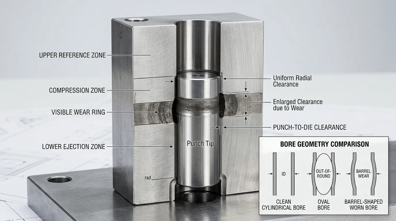
A tablet die bore can experience both dimensional wear and surface deterioration. Dimensional wear changes the bore profile or size. Surface deterioration includes scoring, Pitting, Corrosión, or roughness that may increase friction even when the diameter has not changed significantly.
A wear ring often develops around the working or compression zone. It may appear as a polished band, a change in reflection, or a visible transition on the internal surface. Its presence should trigger dimensional inspection, but it does not establish a pass or fail result.
Bore enlargement changes the functional clearance between the die and the punch tip. When that clearance becomes excessive or uneven, it can contribute to:
- powder leakage between the punch tip and die wall;
- thin fins or flashing around the tablet edge;
- accelerated punch-tip wear;
- poor tablet-edge definition;
- increased friction or inconsistent ejection;
- unstable performance across tools in the same set.
These symptoms are not proof of die wear. Formulation behavior, Lubricación, Ajustes de compresión, tool alignment, Contaminación, and punch condition can produce similar problems. They should be treated as inspection triggers.
Desgaste, Residue, Puntuación, Taper, or Geometric Distortion?
Several bore conditions can resemble wear or produce misleading measurements.
| Estado | Indicación típica | Cómo confirmarlo |
|---|---|---|
| Residuos de producto o filmación | Patchy deposit, sticky surface, unstable readings | Clean the bore using the approved procedure, then measure again |
| Anillo de desgaste | Banda pulida o agrandada localizada | Measure at several depths above, within, and below the suspected area |
| Puntuación de superficie | Arañazos o ranuras lineales | Inspeccionar bajo luz dirigida y evaluar los daños superficiales por separado del diámetro |
| Reducción intencionada | Cambio dimensional gradual a lo largo del tubo | Comparar las mediciones con el dibujo de herramientas controladas |
| Ovalidad | Lecturas diferentes en distintas orientaciones | Mide en posiciones angulares consistentes o ejes de perfil |
| Desgaste en forma de cañón | Lectura mayor en el centro que en las posiciones superior e inferior | Comparar lecturas a lo largo de varias profundidades definidas |
| Error de calibre o de operador | Resultados inconsistentes en la misma posición | Recheck zero, Posición de contacto, Limpieza, and measurement technique |
The tooling drawing is essential when a die includes intentional taper or a non-uniform profile. A designed dimensional transition must not be classified as service wear.
Herramientas y datos de referencia necesarios antes de la medición
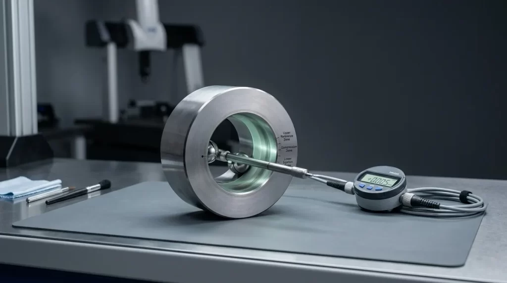
A practical tablet die-bore inspection setup normally includes:
- a suitable split-ball bore gauge or another qualified internal comparator;
- a mechanical or digital deviation indicator;
- the correct setting master or setting ring;
- the controlled tooling drawing and current revision;
- new-tool baseline readings, Cuando esté disponible;
- directed lighting or a bore-inspection light;
- approved cleaning materials;
- an inspection record linked to the die or tooling-set ID;
- evidence that the instrument is within its calibration or verification period.
A split-ball bore gauge measures deviation relative to a reference rather than producing a complete geometric scan. The probe must match the bore range and profile being inspected. Original instrument documentation, such as the guidance for a Sonda de bola dividida y maestro de ajuste, should control the setup and handling method.
Calibration status alone does not prove that the measurement method is suitable for the decision. The instrument must also have enough resolution, Repetibilidad, and measurement capability for the inspection limit being applied. El Guía del NIST sobre trazabilidad metrológica distinguishes traceability from fitness for a specific measurement purpose.
Calibre de bola dividida frente a manómetro de enchufe
| Método de inspección | Uso principal | Limitaciones |
| Calibre de bola dividida | Mide la desviación comparativa a profundidades y orientaciones seleccionadas | Requires correct zeroing, Alineación, contact selection, y técnica de operador |
| Manométrica fija de bujía | Confirma si un calibre fijo puede entrar en un diámetro | No cuantifica el aumento localizado ni el desgaste del mapa por profundidad |
| Inspección óptica o de coordenadas | Puede evaluar perfiles complejos cuando está correctamente configurado | May require specialist equipment, Accesorios, Software, and validated access to internal features |
A plug gauge can support a pass/fail check for a defined size, but it is not a complete substitute for localized wear measurement.
Dibujo, Nominal Size, and New-Tool Baseline
Before measuring, confirmar:
- the correct die or tooling-set ID;
- the correct drawing revision;
- the nominal bore profile and units;
- whether the die has an intentional taper;
- the reference positions used for dimensional control;
- any measurements recorded when the die was new.
The nominal drawing dimension defines the intended design, while a new-tool baseline records the actual starting condition at controlled locations. Keeping both makes later wear trending more reliable.
Cómo medir el desgaste del diámetro del troquel de una tableta
The approved site procedure and the gauge manufacturer’s instructions should take priority over a general guide. The sequence below shows the controls that a repeatable inspection process should contain.
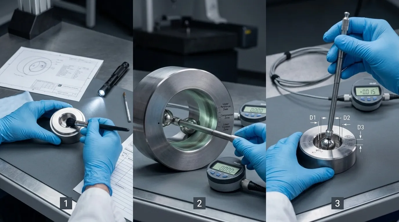
Step 1 — Identify, Limpio, and Visually Inspect the Die
Record the die ID before cleaning or measuring. Confirm the drawing revision and previous inspection status.
Clean the bore thoroughly using the approved method. Product residue, polishing compound, lubricante, or corrosion products can alter the contact between the gauge and bore wall.
Inspect the full internal surface under directed light. Record visible conditions such as:
- a polished or enlarged wear ring;
- scoring or scratches;
- pitting or corrosion;
- grietas, chips, or edge damage;
- residue that remains after cleaning;
- a visible taper transition;
- localized discoloration or roughness.
Photographs can help preserve evidence when unusual damage is found. Para operaciones farmacéuticas reguladas, written cleaning, Mantenimiento, and inspection procedures should follow applicable requirements such as 21 CFR 211.67.
Paso 2 — Establecer y verificar la referencia de calibre
Select the correct gauge range and contact configuration for the bore.
Clean and inspect the setting master. Place the probe in the master according to the instrument instructions, then align or rock it as required to locate the correct comparative point. Set the indicator to zero or to the documented reference value.
Record the gauge and indicator identification. After the complete measurement series, return to the setting master and verify that the reference has not shifted. A changed zero may indicate drift, Contaminación, loose setup, or handling error.
Paso 3 — Mide un troquel redondo a profundidades y orientaciones definidas
Do not rely on a single reading near the bore entrance. Localized wear may exist only in the compression or ejection region.
Define repeatable measurement positions from the tooling drawing and inspection procedure. A typical measurement map may include:
| Región de medición | Propósito |
| Zona de referencia superior | Establece la condición por encima del área principal de trabajo |
| Zona de compresión o anillo de desgaste | Detecta el agrandamiento localizado donde se forma la pastilla |
| Zona inferior o de eyección | Comprueba la región que influye en la liberación de la tableta |
| Puestos de transición adicionales | Confirms taper, barrel shape, or local damage |
At each depth:
- place the probe without dragging or forcing it against the bore;
- align it according to the approved technique;
- record the comparative reading;
- repeat the reading to check consistency;
- measure at additional orientations where required;
- record the maximum, mínimo, and repeated values.
Different readings by depth can indicate localized or barrel-shaped wear. Different readings at the same depth but different orientations may indicate ovality or directional damage.
The exact depths should come from the die geometry and inspection SOP. One universal set of depth values cannot suit every die design.
Paso 4 — Mide los troqueles oblongos y moldeados por perfil
An oblong or shaped die cannot be represented by one diameter reading.
Use the drawing to identify:
- the major axis;
- the minor axis;
- critical radii or profile transitions;
- orientation references;
- measurement locations at each required depth.
Record every result with both its depth and profile orientation. Suitable contacts or a different inspection system may be needed for complex shapes. If the available gauge cannot contact the required surfaces consistently, do not force a result. Escalate the inspection to the tooling supplier or a qualified metrology process.
| Los perfiles | Enfoque de medición mínima |
| Ronda | Profundidades múltiples y orientaciones angulares consistentes |
| Óvalo u oblongo | Major axis, minor axis, and repeated depths |
| Perfil de forma compleja | Drawing-defined contact points, Radios, axes, and specialist method where required |
Step 5 — Repeat, Historial, and Confirm the Measurement Series
Repeat any unstable reading. If repeated values differ beyond the approved measurement-system capability, Comprobado:
- bore cleanliness;
- probe contact position;
- gauge alignment;
- indicator mounting;
- setting-master cleanliness;
- zero stability;
- contact wear or damage;
- Técnica del operador.
The inspection record should contain more than a pass/fail result. Useful fields include:
- die or tooling-set ID;
- drawing number and revision;
- nominal profile;
- measurement depth;
- orientation or axis;
- repeated readings;
- maximum and minimum deviation;
- visual observations;
- instrument ID;
- setting-master ID;
- inspector and date;
- warning, rejection, or monitoring status;
- final disposition.
Recheck the setting master after the measurement series. If the reference has shifted, investigate and repeat affected readings.
Cómo establecer los límites de inspección del diámetro de la placa
There is no reliable universal wear limit for every tablet die.
A numerical example from another manufacturer, Producto, or tooling set may be inappropriate because the acceptable bore condition depends on:
- punch-tip and die geometry;
- original tooling tolerances;
- tablet shape and edge requirements;
- formulation behavior and abrasiveness;
- powder leakage or flashing sensitivity;
- Rendimiento de eyección;
- press condition and alignment;
- measurement-system capability;
- validated process and product history.
Orientación del sector sobre Monitorización del desgaste del punzón y troquel also treats acceptable deviation as product-dependent.
A new-tool manufacturing tolerance is not automatically the same as an in-service rejection limit. The first controls how the tool is produced. The second determines whether a used die still supports acceptable production.
Entradas para límites de advertencia y rechazo
Use controlled evidence to establish two separate levels where appropriate:
- Warning limit: triggers investigation, shorter reinspection intervals, or increased process monitoring.
- Rejection limit: triggers quarantine, removal from service, o sustitución.
The decision should consider:
| Entrada | Por qué es importante |
| Dibujo de herramientas | Defines the intended profile, Taper, and original dimensional requirements |
| Base de nueva herramienta | Muestra las lecturas iniciales reales en posiciones controladas |
| Condición de punta de punzón | Ayuda a evaluar la distancia funcional entre punzonadores |
| Calidad del borde y dimensional de la tableta | Muestra si el equipo sigue produciendo tabletas aceptables |
| Historial de flashes o fugas de polvo | Puede indicar un aumento de la liberación funcional |
| Tendencia de la fuerza de eyección | May reveal friction, Preparación, rugosidad, or wear requiring investigation |
| Formulación e historial de ejecuciones | Ayuda a explicar las diferencias en la velocidad de desgaste |
| Repetibilidad e incertidumbre de la medición | Determina la confianza en lecturas cercanas al límite de acción |
| Recomendaciones de proveedores | Añade orientación específica para el diseño cuando la herramienta exacta lo soporta |
| Validación del sitio y control de cambios | Conecta el límite con el rendimiento aprobado del producto y del proceso |
The limit should be written into the inspection SOP with the reference data, measurement positions, required repetitions, Responsabilidades, and disposition rules.
Cómo manejar resultados límite
A reading close to the action limit should not receive an automatic pass or fail when measurement uncertainty could change the decision.
Use a controlled confirmation process:
- clean the bore and setting master again;
- verify the gauge zero;
- repeat the measurement;
- use a second qualified operator if required;
- compare the result with nearby depths and orientations;
- review recent tablet-quality and process data;
- confirm with a more capable measurement method when necessary;
- quarantine the die until the result is resolved;
- document the final decision.
Cómo interpretar los resultados y elegir la siguiente acción
| Hallazgo de inspección | Acción recomendada |
| Lectura inestable o contaminación visible | Limpio, verify zero, and remeasure |
| Resultado estable dentro del límite aprobado y sin daños inaceptables | Volver al servicio y conservar el registro |
| Resultado cercano al límite de advertencia | Acortar el intervalo de reinspección y revisar las tendencias del proceso |
| Resultado cercano al límite relativo a la incertidumbre de la medición | Cuarentena y confirma con un método cualificado |
| Límite de rechazo superado | Retira el chip del servicio |
| Severe scoring, Grietas, Chips, or unsafe damage | Cuarentena independientemente del diámetro |
| Requisito de dibujo o perfil no está claro | Solicitar revisión de proveedores o ingeniería |
| Desgaste repetido en varias herramientas | Review punch condition, Alineación, Material, Formulación, y condiciones de funcionamiento |
Do not assume that dimensional enlargement is the only rejection reason. Surface damage can make a die unsuitable even when its measured diameter remains within the dimensional limit.
Procesar síntomas que deberían provocar una inspección no programada
An unscheduled die-bore inspection may be justified when production shows:
- rising or unstable ejection force;
- difficult tablet release;
- new flashing or powder leakage;
- unusual punch-tip scoring;
- binding or increased friction;
- a change in tablet-edge definition;
- recurring chipping, Tope, or lamination;
- inconsistent performance among stations using the same tooling set.
Desgastado, Áspero, scratched, or contaminated die surfaces can affect ejection friction, but ejection force also depends on formulation, Lubricación, Geometría de tabletas, y condiciones de compresión. The relationship is explained in this technical overview of Fuerza de eyección en la compresión de la tableta.
These symptoms should trigger investigation, not an immediate conclusion that the die bore is worn.
Errores comunes en la medición del diámetro de la placa
| Error | Posible efecto | Prevención |
| Medición de un tubo contaminado | Falsa ampliación o lecturas inestables | Primero limpia e inspecciona visualmente |
| Usar el rango o contacto incorrecto de la sonda | Mal contacto o valores engañosos | Haz coincidir el calibre con el calibre y el perfil |
| Saltar la verificación del maestro de configuración | Referencia incorrecta | Verifica antes y después de la serie |
| Medición a profundidades inconsistentes | Los resultados no pueden compararse a lo largo del tiempo | Utiliza posiciones definidas por el dibujo |
| Ignorar la orientación | Se puede pasar por alto el desgaste oval o direccional | Ejes de registro o posiciones angulares |
| Solo una lectura | El error del operador puede pasar desapercibido | Mediciones repetidas |
| Inclinación o balanceo excesivo | Valores máximos o mínimos artificiales | Sigue la técnica de calibre calificado |
| Uso de la revisión de dibujo incorrecta | La geometría diseñada puede clasificarse como desgaste | Confirma el control documental antes de la inspección |
| Ignorar la reducción intencionada | La variación normal de diseño puede parecer defectuosa | Compara todos los resultados con el sorteo |
| Confiando únicamente en el estado de calibración | El método puede carecer de resolución o repetibilidad adecuadas | Confirmar la capacidad de medición respecto al límite de inspección |
| Registro solo aprobado o suspendido | Se han perdido las tendencias de moda | Conservar los valores y ubicaciones en bruto |
Frecuencia de inspección, Records, and Wear Trending
Measure new tooling before production use where practical. This creates a baseline for later comparisons.
Después de eso, inspection frequency should reflect:
- tooling usage;
- Abrasividad de formulación;
- previous wear rate;
- product-quality risk;
- process symptoms;
- proximity to the warning limit;
- maintenance or cleaning events;
- the site’s validated procedure.
A fixed calendar interval may be insufficient. A die approaching its warning limit may require shorter intervals, while stable tooling with a documented history may follow the approved routine schedule.
Trend the actual readings by die ID, Profundidad, Orientación, and date. This allows the toolroom to see whether wear is stable, accelerating, or isolated to one region.
Die-bore measurement is only one part of a complete tooling inspection program. Punch dimensions require separate controls; véase Inspección de longitud de trabajo con perforador de tabletas for that adjacent procedure.
For applicable pharmaceutical operations, routine calibration, Inspección, checking, and records for mechanical or electronic equipment should follow written programs such as those described in 21 CFR 211.68.
Cuándo involucrar al proveedor de herramientas
Supplier or specialist review is appropriate when:
- the original drawing is unavailable;
- the baseline condition was never recorded;
- intentional taper or profile geometry is unclear;
- a shaped bore cannot be measured reliably with the available equipment;
- borderline results remain unresolved;
- repeated wear suggests a wider tooling or process issue;
- a replacement die must match an existing tool set.
Provide enough information for a meaningful review:
- tooling and die identification;
- drawing and revision, si está disponible;
- tablet and die profile;
- measurement depths and orientations;
- raw inspection readings;
- photographs of wear or damage;
- punch-tip condition;
- production symptoms;
- the required replacement or review objective.
Listas de SunshinePro Herramientas personalizadas para prensa de tabletas, including punches and dies, and states that custom processing can be based on drawings or samples. When measured wear has reached the approved rejection point or the original profile requires review, the practical next step is to submit the available drawing, Ejemplo, and inspection findings for a replacement-tooling discussion.
Compartir:



Escrito por Sunshine
Al sol, Somos un fabricante y proveedor profesional de componentes de moldes de precisión, ofreciendo una amplia gama de productos para aplicaciones de estampado y moldes de inyección. Nuestro enfoque principal es el punzonamiento de troqueles, Pasadores y fundas eyector, y postes guía y casquillos. Con mecanizado CNC avanzado, Control de calidad estricto, y una fuerte capacidad de producción, Garantizamos la fiabilidad, Piezas de alta precisión, junto con componentes estándar en stock para un suministro global rápido y eficiente.
NOTICIAS
CONSIGUE EL SERVICIO
Con piezas de calidad para todos los presupuestos y personal amable formado para que tu visita sea informativa y sin complicaciones.
